This archived modification involves airbag and steering-wheel components. Use extreme caution and current airbag/steering safety procedures; fabrication errors can affect steering or airbag function.
Procedure
UrS4 Sport Wheel Conversion
This is a description of how to convert a UrS6 Sport Wheel to work on a UrS4 and have the turn signals cancel as designed. The original concept of cancelling ring adaptation was initially written up by Mike DeBlasio in 2004. Credit for the included sketches and “notching” concept goes to Dave Forgie. I believe Dave’s “notching” concept is a significant improvement, and is much stronger. I believe my car is the first to put Dave’s “notching” concept into practice, so proceed at your own risk. Everything seems to be working fine at this point, and my turn signals cancel as designed.
Warning: This project is not for the faint of heart, and should not be attempted by someone without basic fabrication skills. This is due to the fact that you have to adapt the cancelling ring, and if you make a mistake, both the old and new steering wheels will be unusable.
If you’ve decided to give it a go, proceed with caution, and as always, YMMV.
Parts needed:
(1) Sport wheel with 4D0 951 543D clockspring
(1) UrS6 Upper Column Cover (4A1 953 515 H/01C)
(1) UrS6 Lower Column Cover (4A1 953 516 H/01C)
(2) Screws (N 043 851 3)
(2) M3x0.50×8-10mm Flat Head Socket Screws
(2) Speed Nuts (that work with the M3 screws above)
(1) M3x0.50 Nylon Lock Nut
Two part Plastic Epoxy
(1) Set male/female crimp-on spade connectors
Before you start: Read this document all the way through. This cannot be done in one day due to epoxy cure times. Adjust the wheel with TILT all the way up, and the TELE all the way out. Make sure the wheels are straight, and run the drivers seat all the way back.
Disassembly:
Step 1: Disconnect the – battery terminal. Make sure you have the radio code, as you will need it to reset your radio after you re-attach the battery cable. Warning: others have indicated that solely removing the battery power does not completely eliminate the possibility of airbag discharge. Be careful.
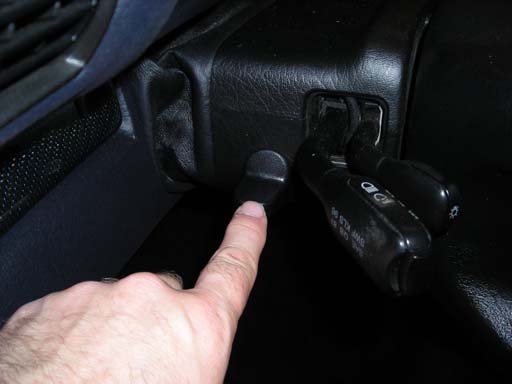
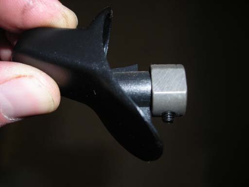
Step 2: Loosen the TILT lever set screw with a 2mm Allen wrench and slide lever off shaft. (Figure 1) Figure 2 shows the removed lever for reference.
Figure 1
Figure 2
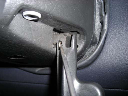
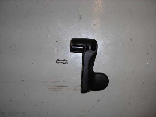
Step 3: Flip Tele lever to its release position to expose retaining clip. Remove clip on TELE lever by hooking the clip and pulling off (Figure 3). Slide lever off shaft. Figure 4 shows removed lever and clip for reference.
Figure 3
Figure 4
Step 4: Remove (2) Phillips screws holding top column cover in place. One is near the TILT lever location, the other is in the recess near the TELE lever location. Both screws are located up in recesses. Lift cover off once screws are removed. Figure 5 shows the lower column cover looking up from the bottom, or the position you will need to be in to remove the screws holding the upper column cover.
Figure 5
Figure 6
Step 5: Locate the red airbag connector (Figure 6). Free up connector from steering column cover and disconnect. I did this from the passenger seat just in case the airbag decided to deploy as I separated the connector.
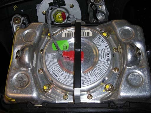
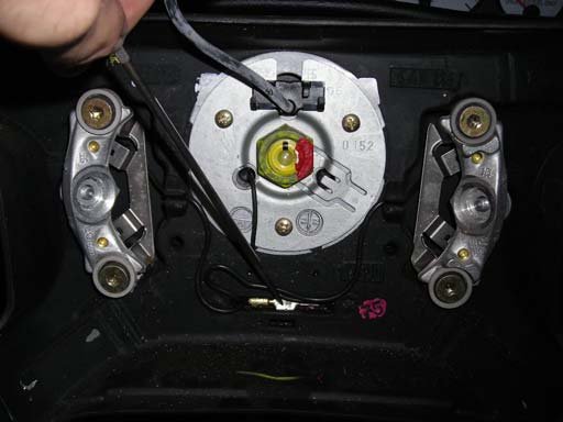
Step 6: Locate and completely loosen the (2) T27 Torx captive screws on the back side of the airbag (Figure 7). Pull the airbag toward you and expose the spring clip holding the connector on the back of the airbag (Figure 8). Release the spring clip, detach the connector, and set the airbag aside.
Figure 7
Figure 8
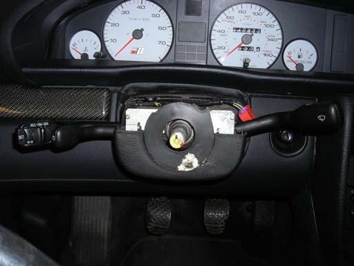
Step 7: Make sure wheel is centered, and remove the 24mm shaft nut (Figure 9). Once nut is removed, wiggle wheel and pull off splined steering shaft. Disregard the pointer indicating the horn connection. This does not have to be disconnected at this location. Figure 10 shows where you should be at this point.
Figure 9
Figure 10
Cancelling Ring Conversion:
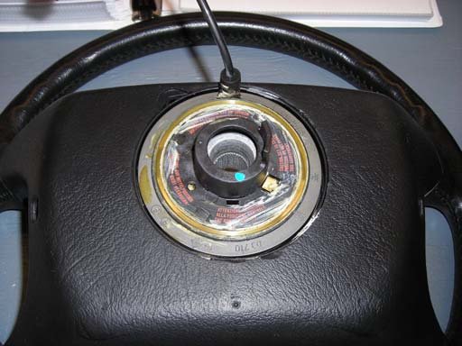
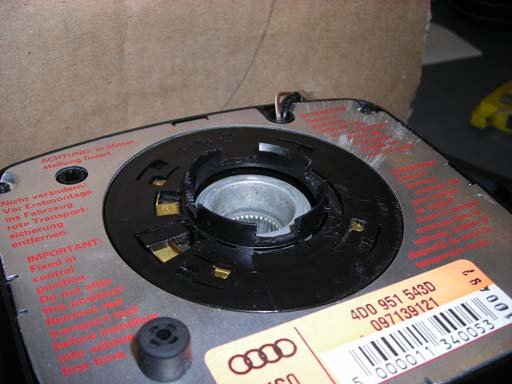
Step 8: Flip your old wheel over and locate the cancelling ring for the turn signals (Figure 11). It is really a ring with a tab.
Figure 11
Sketch 1
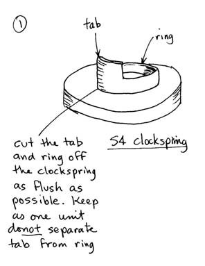
Step 9: Cut the cancelling ring off the wheel flush with the baseplate. This will give you plenty of material to work with later (Sketch 1). I used a hacksaw to get as flush as possible, but I used a Dremel (Figure 12) for everything else, and I think it could have worked as well here. Figure 13 shows what you should have left when you’re done.
Figure 12
Figure 13
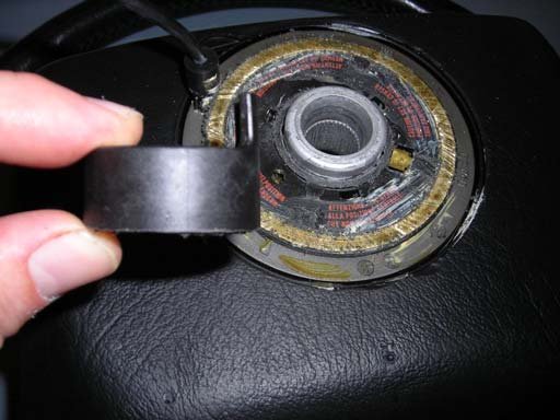
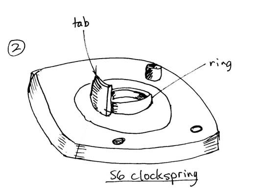
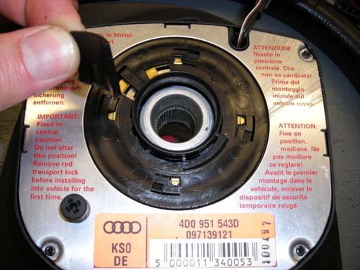
Step 10: Remove the airbag from the sport wheel in similar fashion as described in Step 6. Now flip over the sport wheel and cut off the cancelling TAB only (Figure 14 & Sketch 2). Do not damage the ring. Make sure you mark the centerline of the tab on the ring before removal. You will need this for alignment in Step 12.
Figure 14
Sketch 2
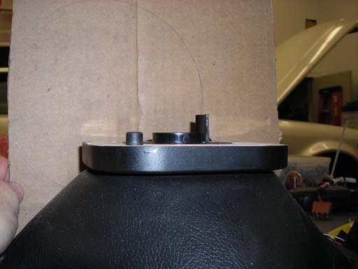
Figure 15 shows what you should have when you complete this step, a removed tab, and an intact ring. Congratulations, you are now past the point of no return.
Figure 15
Figure 16
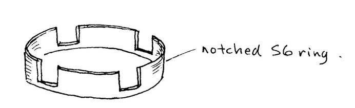
Step 11: Next, you will need to cut four “notches” in the ring you left intact on the sport wheel (Sketch 3). Notch depth is not critical, but make them deep enough to provide enough surface area for a good epoxy bond. I cut mine to within a couple mm of the base of the ring. Figure 16 shows what you should have when you’ve completed this step.
Sketch 3
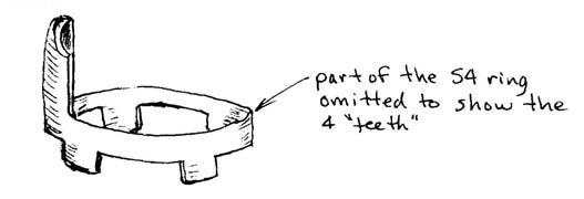
Step 12: Now, you need to cut mirror image “notches” in the cancelling ring you removed from your old wheel. The idea is that the two rings will mate together when you are finished. Sketch 4 shows you the basic idea, but not to scale. Make sure to align the centerline of the tab on the S4 cancelling ring with the mark you made on the S6 ring in Step 10 before you mark your “notches”. If you don’t, your tab will end up in the wrong spot and will not work.
Sketch 4
Step 13: Once you have marked and cut your “notches” in the S4 cancelling ring, you must adjust it for height. Measure and trim your “notches” to get the overall tab height as shown in Sketch 5. Figure 17 shows what you should have when you’ve completed this step.
Sketch 5
Figure 17
Step 14: Next, you need to glue the two rings together to make one as also shown in Sketch 5. Take your time and test fit, trim, test fit, trim, etc. until the two pieces mate together well (Figure 18). Use a two-part plastic epoxy. Cover both contact services with the epoxy, and then cover the inside and outside of the joint for added strength. Let the assembly sit for at least 24 hours to cure. You don’t want it coming apart after you’ve re-mounted the wheel. Figure 19 shows the glued assembly.
Figure 18
Figure 19
Lower Column Cover and Re-Assembly:
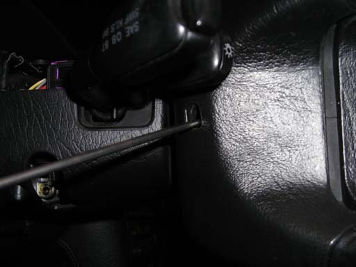
Step 15: The lower column cover is attached with (3) Phillips head screws into knurled captive nuts in the cover itself. Figure 20 shows how I got the top screw loose. There are two towards the bottom also. This means you have to contort yourself under the steering column, bend down the column cover, and slide a long, narrow Phillips screwdriver into the column cover from the front to get to the screws. You’ll need a flashlight as the screws are short, not long like the top one. This step is a real PITA. Once loose, remove the cover, and pop the horn connection (brown wire) out of its slot.
Alternate method: You could also just pry between the cover and switch faceplate. This pulls the knurled nuts out of the S4 lower cover, but it just seemed like something was going to break to me. If you are successful, I understand it is possible to open up the holes in the column cover slightly and push it on over the knurled nuts now exposed for a friction fit. I wanted easy removal in the future, so I chose to develop the other method.
Figure 20
Figure 21
Step 16: Now that you have removed the lower column cover, you will see that you are in somewhat of a pickle as the S6 lower column cover has holes instead of a spot for the knurled captive nuts. Pull out the hardware you purchased as shown in Figure 21. The long screw is the top screw you removed in Step 15. The speed nuts will need to be modified (or did in my case). Get speed nuts that are narrow enough to fit in the recesses where the lower screws were located. About ¼” width speed nuts should work. The speed nuts in my case were narrow enough to fit in the recess, but too long, so I ground them a little shorter (Figure 22). Next, loosen, do not remove the screws holding the metal plates on the front of the column switches. This will allow you to test fit, and ultimately install the speed nuts by slipping them over the plates (Figure 23). Re-tighten the plate screws.
Figure 22
Figure 23
Step 17: Next, install the S6 lower column cover. Make sure the pins interlock into the holes on the column boot, otherwise it will not expand with the column when you telescope the wheel towards you. Insert the horn wire through the hole in the new column cover. You will see that the two lower holes line up fine, but the top hole is too high. Install the 3mm flat head socket screws into the speed nuts. I used flat head to make sure I had no interference with the clockspring once the wheel was re- installed. Drill out the hole for the top screw, and re-install the long screw in reverse orientation from the way you took it out. Install the 3mm locknut you purchased, and tighten so that the screw head pulls into the plastic some to prevent clockspring interference. Figure 24 is what you should have at this point.
Figure 24
Figure 25
Step 18: Clip the connectors off the brown horn wires on the column and the sport wheel. Install new connectors. I used insulated crimp-on spade connectors so I could disconnect it in the future if necessary (Figure 25).
Step 19: If you were part of Dave Forgie’s wheel insignia GB, now is the time to install it. Pry out to old, and press in the new (Figure 26 & 27).
Figure 26
Figure 27
Step 20: Install the sport wheel on the shaft making sure it, and your wheels, are both straight. Re- install the 24mm shaft nut and torque to 40nm.
Step 21: Install the sport wheel airbag by mating the electrical connector to the back of the airbag and re-install the airbag on the sport wheel.
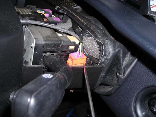
Step 22: Route the horn and airbag wires over the top of the steering column and mate the connectors. I did this from the passenger seat just in case. I found that the airbag connector would not allow proper installation of the S6 upper column cover when seated in its original S4 location (Figure 28). I tucked it in the recess as shown in Figure 29 instead. The blue connector is the horn connection.
Figure 28
Figure 29
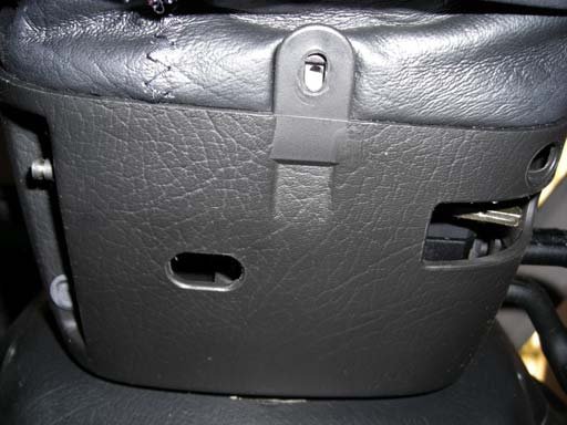
Step 22: Install the S6 upper column cover. This is tricky as there are two “catches” on the lower cover that fit into slots on the upper cover, and they break off easily. You also have to get the front positioned so the screw holes line up top to bottom. It took me a few minutes (read PITA) of messing around to get it positioned correctly. Make sure you also catch the holes in the column boot for the same reason as explained in Step 17. Hold everything in place and install the two Audi screws you purchased up from the bottom in the holes provided in the lower column cover.
Step 23: Re-connect the battery. Re-set your radio code.
Step 24: Re-install the TILT and TELE levers and you’re done. I have heard that others have had trouble with getting the S4 TILT lever to work with the S6 column cover due to the width of the S4 TILT lever. Mine seems to work fine. Worst case, source an S6 TILT lever from one of the used parts sources available. Congratulations!
Steve Young 94UrS4
Additional Photos

Related Tech Tips
Revision History
- — Updated
