Archived installation procedure. The optional section describing melting lead wheel weights reflects period practice; use modern safer weighting methods and current lead-handling guidance instead.
Procedure
UrS4/6 Europrice SSK Installation
While this write-up is specific to the Europrice SSK, it should be applicable to any SSK that replaces the whole shifter assembly, and can be used to R&R the stock shifter assembly if replacing worn parts. Read though the whole procedure first, as there are some reference marks that will be useful during reassembly. Make sure your shifter is in neutral.
Step 1: Remove rear console. This is described in a separate write-up.
Step 2: Remove front console. This is described in a separate write-up.
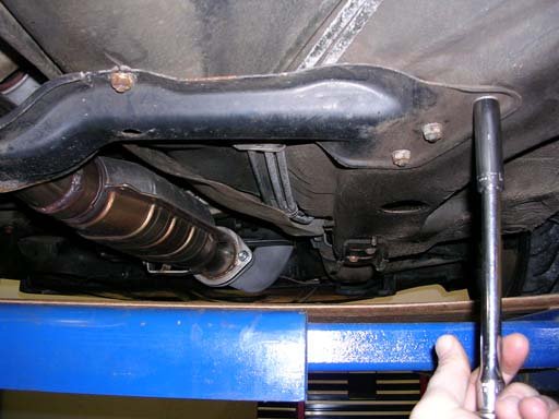
Step 3: Remove crossmember. Crossmember is held on with ten (10) 13mm nuts (Figure 1).
Figure 1
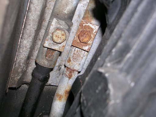
Figure 2
Step 4: Separate exhaust system from downpipe. If you have a Stromung, you will need to remove the center section only. If you have a stock system, you may get away with only having to remove the cats, but will probably have to slide the rest of the system rearward for clearance to work.
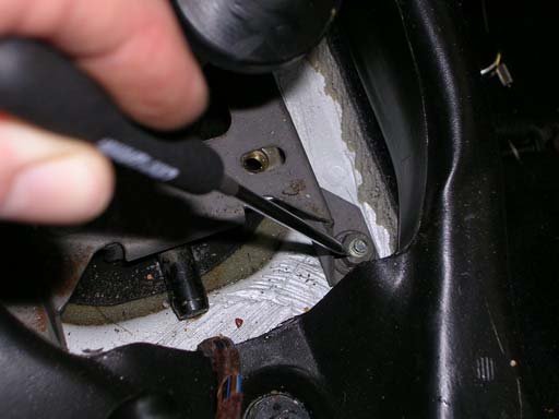
Step 5: Remove two (2) 13mm retaining bolts from torque rod and shift rod connections (Figure 2). Along extension on a 3/8 ratchet worked for me. You shouldn’t need a universal joint. Mark the torque and shift rods for insertion depth into the forward rods for reference before removal.
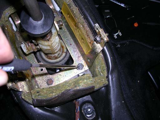
Step 6: Remove the four (4) 10mm bolts holding the top portion of the stop bracket, and remove the bracket (Figure 3). Take notice of bolt positions as these hold the rear locator that accepts the pin on the rear of the shift assembly.
Figure 3
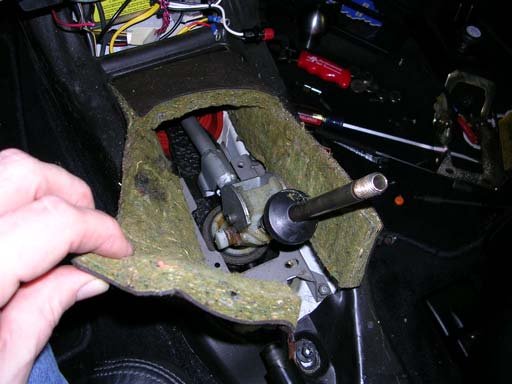
Figure 4
Step 7: Remove the insulation blanket from around the shifter assembly (Figure 4).
Step 8: Remove the four (4) 10mm nuts holding the lower portion of the stop bracket, and remove the bracket (Figure 5).
Figure 5
Figure 6
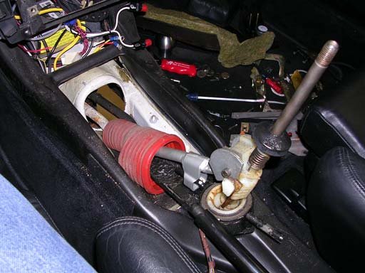
Step 9: Remove the whole shifter assembly with weather boot by lifting up and out towards the rear. You may have to wiggle it slightly to get everything moving (Figure 6). Don’t be concerned with the splines on the torque and shifter rods. The forward rods attached to the transmission are not splined on the inside at the connection points.
Step 10: Clean and transfer the weather boot to your SSK. Measure and transfer your insertion depth reference marks made in Step 5 to the SSK rods.
Weighting of SSK shift rod
If you do not plan to weight your shift rod, skip this section and go to the Reassembly Tips section.
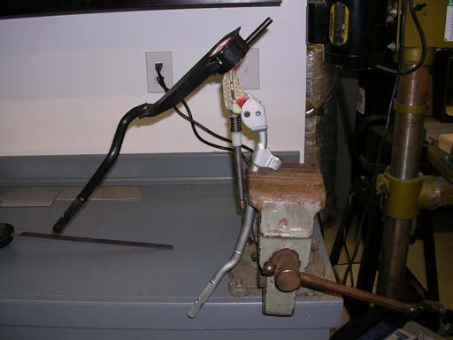
Step 11: Lock your SSK in a vise as shown (Figure 7).
Step12: I went to Pep Boys to ask if I could grab some used wheel weights out of the junk bucket next to the tire changer. While I was rummaging through to find the cleanest ones I could, one of the mechanics came up and gave me a box of brand new ones. Score! Anyway, you need to obtain some lead wheel weights. I used approximately 14oz of weights to fill up the hollow in the shift rod.
Figure 7
Figure 8
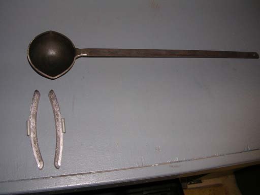
Step 13: Remove the steel clips from the wheel weights. Heat the weights in some type of container. I used a plumber's ladle (Figure 8) I had which was used for running lead plumbing joints way back when. You can still get these from plumbing supply houses for around $35 if you are so inclined. I used an acetylene “B” tank for my heat source.
Step 14: Heat the weights until they liquefy, and pour into the shift rod (Figure 9). You should probably wear a mask when heating the lead as I’m sure lead fumes are not good to inhale.
Figure 9
Re-assembly Tips
Step 15: I used anti-seize on the torque and shift rod ends to facilitate disassembly again in the future. Reinstall the SSK through the opening in the floor. Line up the rod connections from underneath. There are no splines on the inside of the forward rods, so don’t worry about alignment. Get the retaining bolts started to keep everything from coming apart.
Step 16: Reinstall the lower portion of the stop bracket, and tighten. Make sure you slip the rubber support over the pin on the rear of the shifter assembly. Reinstall the top portion of the stop bracket. Before tightening the bracket in place, make sure your transmission is still in neutral, and align your side-to-side shifter assembly position (for neutral). Tighten down the top portion of the stop bracket.
Step 17: Set the front-to-back shifter assembly position (for neutral) by adjusting to the marks on the torque and shifter rods made in Step 5. Tighten the torque and shift rod retaining bolts. Reinstall the insulation blanket around the shifter assembly.
Step 18: Reinstall your front and rear consoles and you’re done.
Steve Young
Additional Photos
Related Tech Tips
Revision History
- — Updated
