Archived period audio retrofit for 1995.5 cars. Phatnoise hardware and referenced suppliers may be obsolete; preserve wiring information as historical guidance.
Procedure
Phatnoise/Concert 1 Head Unit Installation Procedure
This installation procedure is intended for the owner who is new to wrenching on his car. It will be infuriatingly detailed for someone who has had this area of his car apart prior to reading this. This installation procedure is for 95.5 cars only! I have not ironed out the installation for the 92-95 cars with the Gamma head unit. The Concert 1 head unit was selected due to its similar wiring to the original factory Delta head unit. Special thanks must first go to Tom Mullane for the original idea, and for his general write-up, of which the relay installation section in this document is humbly used without permission. Sorry Tom! If you already know how to disassemble these areas of your car, and you have all the parts, this process should take you approximately 4-6 hours.
STEP 1: OBTAINING THE PARTS
The Phatnoise system has both an Audi version and a VW version, but don’t fret, as they are the same animal. I went with the VW version as it is less expensive. They are available via eBay for around $150. Make sure you get the whole setup including USB cradle and DMS cartridge. There are some out there that are the Phatbox only. Buyer beware.
The Concert 1 head unit is also an eBay item. They were standard issue in the early C5 A6 car according to Tom M. Hold out for one in the $100 price range, they are out there. Make sure it comes with the code, although it seems that many of them start right up without one (mine did).
Get the VW Beetle harness (p/n 1J0-051-592A) as it is the least expensive harness that will work. (Tom M. says to use the Audi C5 A6 harness if you are using the Audi Phatbox.)
Get mounting bracket (p/n 1C0-098-201). This worked great for mounting in my Avant. I believe it should work fine in a sedan also. This part is listed as a CD changer mounting bracket, but don’t panic.
Ken @ VW of West Hartford CT (860-236-9164) can get you all of this stuff at great prices and will ship to you.
STEP 2: REAR SEAT REMOVAL
To access the battery, you will need to remove the rear seat bottom. Stick your head down into the rear seat footwell and look towards the rear of the car. There is a Phillips head screw on each side. Remove these two screws. Lift up on the seat bottom, but be careful as you will have to disconnect the seat heater wiring harnesses (one each side). Lift the seat bottom out and set aside. Disconnect the negative battery terminal for safety.
STEP 3: RADIO REMOVAL
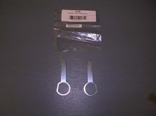
You will need special tools (Figure 1) to remove the head unit. They are available via eBay shipped for under $15, which is where I obtained mine. Some forum members have fabricated their own tools, I chose the easy way.
Figure 1
Figure 2
Insert the tools in the slots at the bottom of the head unit as shown in Figure 2. The tools will retract the pins holding the head unit in and will serve as handles for pulling the head unit out of the console. Once you have released the head unit, pull it out and inspect the connections at the rear.
Figure 3
Figure 4
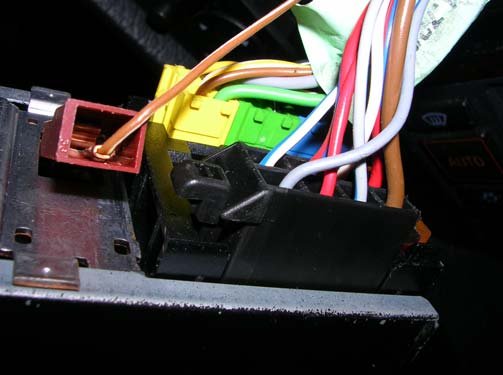
Figures 3 and 4 show you what you should see. Disconnect the wiring connectors and the antenna cable and set the head unit aside.
STEP 4: DOOR SILL TRIM AND UNDER DASH REMOVAL
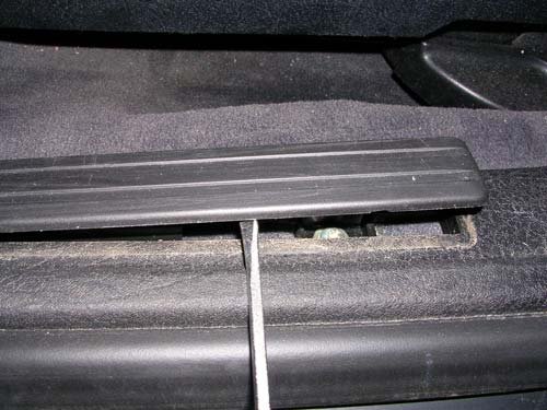
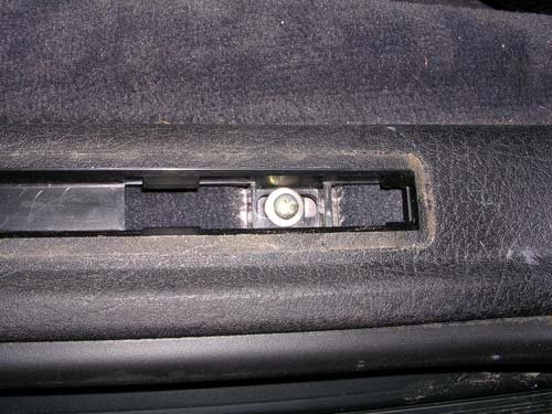
You now need to open up the path you will use to route the new Phatbox harness to the rear of the car. My car is an Avant, so the CD changer is mounted on the driver’s side. Sedan owners will probably want to go along the passenger’s side. Door sill trim removal will be the same, under dash removals (glove compartment) will be somewhat different. Pry up the door sill trim as shown in Figure 5. Remove the screws underneath the trim just removed (Figure 6). There should be three in the front door area and two in the rear door area.
Figure 5
Figure 6
Once the screws are removed, pry the trim away from the b-pillar. This is one long piece, but should pop loose without much trouble. Figure 7 shows what this trim piece looks like.
Figure 7
Figure 8
Now look under the dash. There are two 10mm bolts (Figure 8) holding the lowest dash panel in place. Remove these two bolts and slide the trim piece towards the rear of the car out of the retaining slots. Figure 9 shows the shape of this trim piece for reference. Next, pry the bolt covers out of the lower dash panel as in Figure 10.
Figure 9
Figure 10
This panel is secured with four 10mm bolts. Two under the covers just removed, and two that are exposed by removal of the previous trim piece (Figure 11). After the four bolts are removed, slide the panel towards the front of the car and down out of the retaining slots. Figure 12 shows the shape of the piece just removed for reference. By the way, this is a great time to replace that broken gas pedal assembly! With the dash apart, it takes about 5 minutes.
Figure 11
Figure 12
Next, you need to remove the kick panel. There is a hidden Phillips head screw under a pop out cover at the bas of the kick panel (Figure 13). If you do not remove this, you will break the kick panel. Remove the screw, and pull the kick panel gently towards the rear of the car out of the snap–in retaining brackets. Figure 14 shows the removed kick panel for reference. Sedan owners, you will need to remove the passenger side door sill trim, kick panel, and possibly the glove compartment for proper access to run your new harness.
Figure 13
Figure 14
STEP 5: WIRE K-LINE
The K-line is what VAG-COM uses to talk to the car. This will allow you to tell your Concert 1 head unit that your car has BOSE, and read radio diagnostics with VAG-COM. Find the wire (red with blue stripe) that is on pin 3 (Figure 15) of the black connector you disconnected
from the back of the radio. You will need a 4’ section of wire of similar gauge to the red/blue stripe wire at this point.
Figure 15
Figure 16
There are two wires color-coded the same, so make sure you get the correct one. Figure 16 shows where I ran my wire up from under the dash to the radio opening. Tape the head unit end (blue/green/yellow connectors) of the new VW harness to your 4’ piece of wire and feed both up through the console to the radio opening at the same time. There is plenty of harness so don’t be leave yourself short at this end. I pulled about 6” out through the radio opening. Separate the harness from the K line wire. Use a butt splice to attach your 4’ wire to the cut end of the wire from the connector as shown in Figure 15. Tape off the cut end of the harness (you may need this later). Figure 17 shows where I entered the rear of the console from under the dash.
Figure 17
Figure 18
Leave the rest of the wire coiled up in the driver’s side footwell. Now open the hood and find the relay board housing. It will be near the base of the drivers side windshield wiper arm. See Figure 18.
Figure 19
Figure 20
Remove the cover by releasing the spring clip, and lift off the top. Slide something down through the relay box into the footwell area. With a flashlight, you can see all the way through. I used a spring loaded gripping tool, and grabbed the wire in the footwell and pulled back up through. See Figures 19 and 20. Cut wire to length, and attach a ring terminal large enough to fit on the K terminal post. The K terminal is identified in Figure 21.
Figure 21
Figure 22
Once you have installed the ring terminal under the 8mm nut on the K terminal (Figure 22), re-install the relay box cover and close the hood.
STEP 6: RUN NEW HARNESS
Tuck the harness up under the dash as you run it across to the kick panel area. If you release the duct from its retaining clip shown in Figure 23, you can route the harness up behind it and out of the way. Leave the brown ground wire loose. Remove the nut holding the under dash relay panel and fasten the ring terminal on the brown wire here (Figure 24). Make sure you locate the ring terminal against the metal behind the plastic bracket. Figure 25 shows how I routed my harness through the kick panel area.
Figure 23
Figure 24
Lift up the edge of the carpet and tuck the harness underneath. Figures 26, 27, and 28 show the routing along the door sill. Make sure you locate the harness to prevent chaffing on sharp edges. Route the harness up over the seat track (Figure 28), there is no way under.
Figure 25
Figure 26
Figure 27
Figure 28
Once you get to the rear seat area, feed the harness up under the metal framework and into the rear seat cavity along with the other wiring already there. Figures 29 and 30 show the route I used.
Figure 29
Figure 30
Now comes the tricky part. You have to get the harness up and over the rear wheelwell. I only loosened the trim in this area rather than remove it. There is one Phillips screw located down low on the wheelwell near where you removed the door sill trim (Figure 31).
Figure 31
Figure 32
The tab, as you can see, was already broken. Remove the screw, and you can pry the trim away from the wheelwell area enough to push the connector up behind the trim (Figure 32). Keep pushing the harness in while holding the trim away from the body. Then go to the rear cargo area and open the CD changer compartment and look inside towards the front of the car for the harness connector. Figure 33 shows the harness connector as it appeared after feeding the harness over the wheelwell. It is hard to see, but the harness connector is at the center of the photo. Grab it with the gripping tool used earlier (Figure 34), and pull the remainder of the harness through to the cargo area. Now you are ready to test the Concert 1 head unit.
Figure 33
Figure 34
STEP 6: RADIO TEST
Think back to when you disconnected the Delta head unit. Remember the blue/green/yellow connectors (Figures 3 & 4)? Good. Separate the blue connector from the other two on the factory harness (they clip together) and tape back out of the way. Unclip the green/yellow empty connectors from the blue on the new harness, and clip the blue new harness connector to the green/yellow factory harness connectors. Plug this new combination harness connector group to the rear of the Concert 1 head unit. Plug the black factory connector next, and then the brown ground spade connector and the antenna lead. Slide the head unit into the console slot part way. Reconnect the negative lead on your battery. Turn on the head unit and use your code if necessary. If you get sound, make sure all your cabling is secured nice and tidy and push the head unit in until it clicks. Then reinstall all the trim and the rear seat in reverse order. Skip to Step 7. If you get no sound, go to Step 6a.
STEP 6a: RELAY INSTALL
I did not have to add a relay during my install, so this section is included from Tom Mullane’s generalized write-up. This relay install was developed for Marc Swanson’s Avant. The reason you have no sound is that the amplifier trigger wire is not getting the proper voltage in order for the amp to turn on. As a result, the head unit lights up and can be tuned, but the speakers are not enabled. The trigger wire comes out of the yellow connector at pin 15 (Figure 35). You will need to cut the wire a few inches back from the connector and wire in a relay here. Radio Shack sells micro-relays that should work well. The wire coming out of the radio at pin 15 becomes relay coil trigger. Relay coil ground can be the radio case. Wire the normally open relay contacts to the red/blue stripe wire you cut and taped earlier as part of the Step 5 K line modification (power), and the harness wire you just cut off pin 15 (load). When the radio attempts to enable the speakers, it now only has to power the micro-relay coil. When it pulls in the coil, the normally open contacts will close and put full power to the amplifier to enable the speakers. You should now have sound. Thanks again to Tom and Marc for this section.
Figure 35
STEP 7: REMOVE THE CD CHANGER AND MOUNT THE PHATBOX
Undo the strap and pull up to remove the CD changer protective cover (Figure 36). Remove the two Phillips screws (one each end) that secure the CD changer bracket to the floorpan (Figure 37).
Figure 36
Figure 37
Lift out the CD changer and mounting bracket as a unit. Remove the four 7mm bolts and separate the CD changer from the mounting bracket. Figure 38 shows what my mounting bracket looked like. Figure 39 shows the pieces of the Phatbox mounting bracket.
Figure 38
Figure 39
Take the U shaped piece of the mounting kit in Figure 39, and set it on top of your old CD changer bracket. Do not center it on the old bracket. You need to offset it in both directions to make sure you have metal under each hole, and to leave enough room for the protective cover piece of the new bracket kit to fit properly. Locate the two outermost holes in the bottom of the new bracket. Using a scratch awl, mark these holes on the old bracket for drilling. Drill these two holes and find a couple machine screws/washers/nuts to bolt the two brackets together. Figure 40 shows what your assembly should look like. Attach the two flat pieces of the new mounting kit to the Phatbox with hardware provided (Figure 41).
Figure 40
Figure 41
Connect the harness that came in your Phatnoise box to the base of the Phatbox now. Tighten the thumbscrews. Slide the Phatbox into your custom bracket assembly (insert the protective cover first) and attach with hardware provided (Figure 42). The instructions with the new bracket are helpful here. Holding everything lined up and getting the screws started can be interesting.
Figure 42
Figure 43
Set your assembly back into the original CD changer location and mount to the floorpan with the original two Phillips screws. Coil up and secure your extra harness, BUT DO NOT MAKE THE FINAL CONNECTION YET. From here, follow the Phatbox startup procedure. You can screw things up if you put power to the Phatbox at the wrong time.
Congratulations, you’re finished! Just like the factory would have done it. Enjoy your tunes!
Steve Young
Additional Photos








Related Tech Tips
Revision History
- — Updated
