
Archived modification affecting ABS operation. Laws, safety expectations, and vehicle-use conditions vary; review carefully before modifying the braking/ABS system.
Procedure
’94 UrS4 ABS Switch Modification
While driving at the world-famous Sundridge UrS-car ice races last year, I found myself wishing I could turn off the ABS on my ’94 UrS4. I began accumulating parts to install my own ABS defeat switch. During the first ice storm this year as I was rolling towards an intersection with the ABS yammering away and not much stopping going on, I thought “This is freaking crazy, I need to be able to shut the ABS off” – so I installed the ABS defeat system I had planned last year.
Disclaimer
With this modification, you are installing a system that disables a “safety feature” on the car. In almost all situations, it is better to have the ABS on. Under certain situations (slow speed/slippery surface, deep snow, gravel) it may be advantageous to have the ABS switched off. Audi used to install Antilock switches that would turn off the ABS but eliminated the switch in 1993. It is rumored that this was done to minimize potential liability in the U.S.A. if some doofus turned off the ABS, had an accident, and decided to sue Audi for fitting a switch which would allow a doofus to turn off the ABS.
If you install this modification, realize what you are doing. If you sell the car, you may want to reverse the mod to restore the ABS to its “undefeatable” status. The mod is designed to permit this.
Also be aware that if you screw up the installation, you can end up with no ABS. There are lots of sharp metal edges in there, and if you don’t route the wiring correctly and protect it, you can short a power wire, blow the fuse, and bingo! no ABS. If you do the above AND install the mod upstream of the fuse by picking the wrong wire from the fusebox, you can have a nice harness fire and maybe burn the car to the ground while skidding out of control at high speed on an icy road with no ABS.
So, to make a long-winded ramble short, what is presented herein is a description of what I have done to my car to permit me to choose when ABS is on and off. I am not recommending you do this to your car, but if you so choose you can take a look at what I’ve done and decide for yourself whether to accept the responsibility for modifying your car using this or another procedure.
Also note that I assume in my description of the procedure that you have the basic knowledge necessary to perform this type of mechanical and electrical work – I don’t cover all the detailed steps of the installation.
Hack, cough, ptew – got a bad taste in my mouth for some reason….
Design Babble
The primary design parameters for the mod were as follows:
1. Dash mounted switch OEM in appearance. 2. Easily reversible to stock 3. Components fail to ABS “on”
The OEM Antilock Switch System The ’92 UrS4 had an ABS relay mounted in the left side A-pillar kick panel. The dash mounted “Antilock” switch was a momentary switch that pulsed the relay, causing it to shut off the ABS system. The dash switch was fitted in the ’92 UrS4.
’93 – ‘94 UrS4 & UrS6 Sometime in the ’93 model year it appears Audi eliminated the ABS relay and went to the EDL style ABS controller. This controller is fed power through a dedicated fuse in the fusebox (the earlier models had the fuse in the top of the ABS relay, not the fusebox). Pulling the fuse shuts down the ABS.
Will the Mod Work on Your Car?
Check the main fuse panel in the left end of the dashboard. If there is an ABS fuse in position 21, this mod will work for you (see Photo 1).
The Modification
The mod fits an OEM foglight switch sporting an Antilock switch faceplate in a blank slot in the dash switch panel. The switch controls a normally-closed relay which will interrupt the power to the ABS controller when the switch is “ON” and the relay is activated. The relay is installed on the wire FROM the fuse TO the ABS controller – it is downstream of the fuse and is protected by the fuse. If the relay fails or the switch fails to close, the ABS will be “ON”. If a wire is improperly routed/protected and shorts to ground, the fuse will blow and the ABS will be “OFF”, but your pants won’t be on fire.
NOTE: Unlike the OEM Antilock switch system, this mod will not “reset” the ABS to ON if you shut off the car and restart it. If it is switched OFF when you shut off the engine, it will still be OFF when you restart the car (thanks, Igor!).
The electrical schematic is shown in Figure 1 below.
Figure 1 UrS4 ABS Switch Installation
Legend: black = existing wiring colour = new wiring
Terminal 15 on central electrical panel
1.5 sw
5/58a
1/15a
200q rear foglight switch with "Antilock" faceplate
ABS Fuse #21
S21 15A
2/31
6/NS
85 87
87a
Bosch relay 0 332 209 150 12V 20/30 A
ABS fuse connector & wire removed from fusebox
Ground on central electrical panel
T21a
1.5 sw/gn
The Antilock Switch
Parts required: 1 rear foglight switch from a ‘89-’91 200q 1 antilock switch from a ‘89-’91 200q or ’92 S4 1 connector block & 6” associated wiring for one of the above switches (the blocks for both switches are identical) Assorted bits of wire and terminals
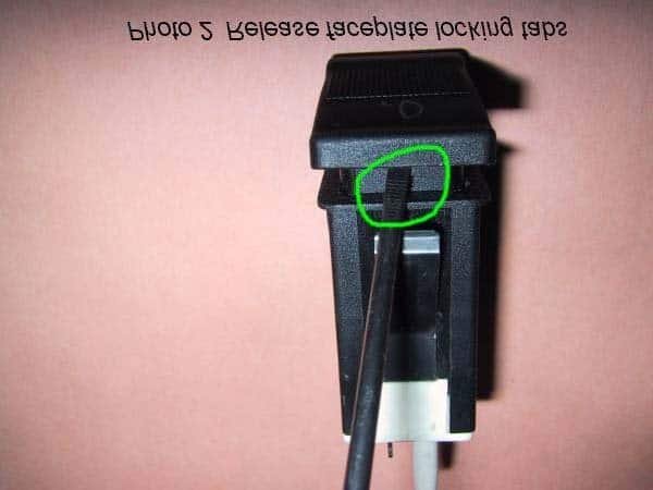
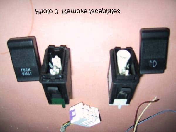
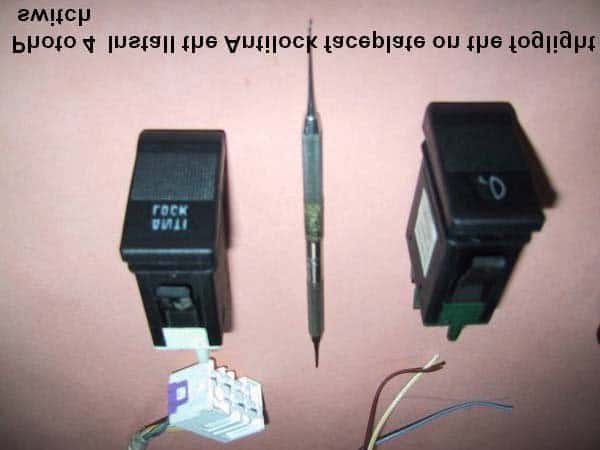
1. Remove the faceplates from both switches by depressing the tabs which secure the faceplate (see Photos 2 & 3). 2. Remove the bulb from the lower bulb socket on the foglight switch. Check that the faceplate illumination bulb in the upper socket is OK. 3. This is a good opportunity to clean the contacts and terminals on the foglight switch – it is 10 years old or so. 4. Install the antilock faceplate on the foglight switch (see Photo 4).
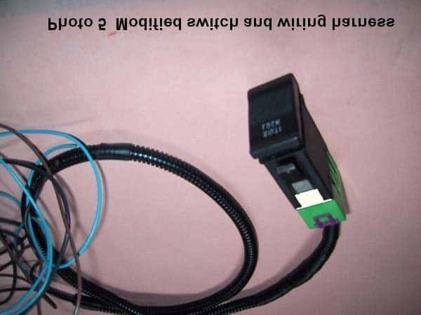
5. Extend the four wires on the connector block – you’ll need about 3 feet of wire. Protect the wiring loom with spiral wrap tubing or equivalent (see Photo 5).
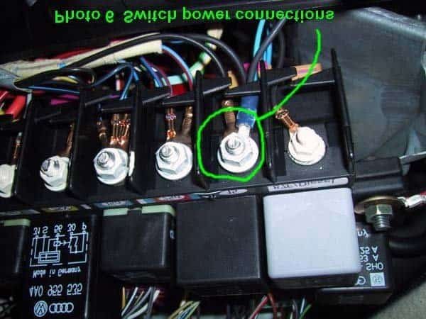
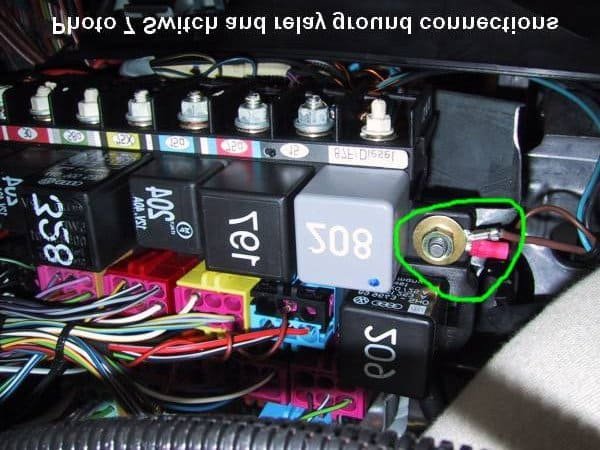
6. Install the switch in the empty leftmost switch bay. Run the wiring loom through the dash under the steering wheel mechanism over to the general vicinity of the fusebox. 7. Connect the power wires (switch terminal 5/58a to the switch contacts and terminal 1/15 to the illumination bulb) to terminal 15 on the CEP (Central Electrical Panel) under the driver’s side of the dash (see Photo 6). Terminal 15 is switched power that is only on when the ignition switch is on. 8. Connect the wire from switch terminal 2/31 (illumination bulb ground) to the mounting bolt for the CEP (see Photo 7).
The Fusebox Mod
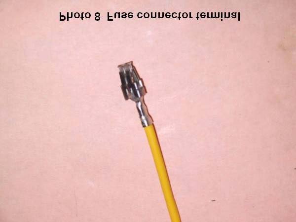
Parts required: 1 fuse connector terminal & wire (available from an Audi dealer, see Photo 8, sorry, can’t isolate the PN from all the other connectors I bought at the same time)
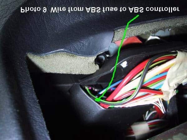
The black/green wire from Fuse 21 to the ABS controller is shown in Photo 9. To keep the mod reversible, I removed this wire and fuse connector from the fusebox and installed another fuse connector and wire to connect the fuse to the relay. To reverse the mod, the new connector and wire will be removed and the original put back in.
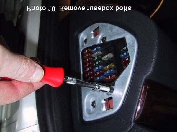
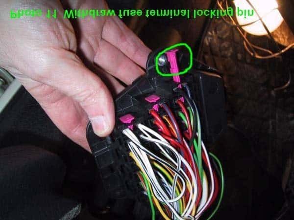
1. Remove the 2 bolts securing the fusebox (see Photo 10). 2. Slide the fusebox out of the dash so that it is hanging from its wiring harness. 3. Slide the back cover off the fusebox. Note that this SLIDES off; don’t try to pry it off or you’ll break something (don’t ask how I know this…). 4. The fuse connectors are physically locked into place with purple plastic pins. Remove the pin locking the connector on the black/green wire (see Photo 11). MAKE SURE YOU REMOVE THE CORRECT CONNECTOR! If you get the power side of the fuse (black wire), the relay and wiring will not be protected, in which case a short to ground could lead to a under-dash fire and a crotch full of burning plastic. I’m quite sure that would ruin your entire day. Verify the power
side with a VOM before pulling the connector to make sure Hans und Franz didn’t get the wire colour codes mixed up.
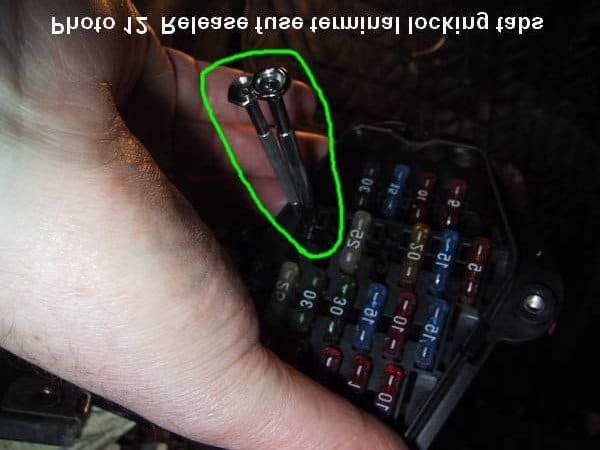
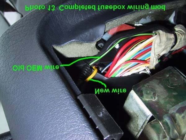
5. Depress the locking pins on the fuse connector (see Photo 12) and pull it out of the fusebox. 6. Insert the new fuse connector and wire into the fusebox. Re-install the locking pin, the fusebox cover, and the fusebox. Photo 13 shows the completed fusebox wiring mod.
The Relay
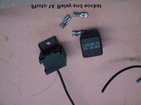
Parts required: 1 Bosch NC (normally closed) relay, 12V, 20/30A, PN 0 332 209 150 1 Bosch relay socket PN 334 485 008 4 Bosch female tab connectors for the relay socket. These are special metric size connectors. Normal ¼” connectors are too small to fit properly (see Photo 14).
The relay switches the power to the ABS controller off and on. The relay is normally closed, so power is connected to the ABS controller. When the dash “Antilock” switch is pushed and engaged, the relay activates and switches the power to the controller off. If the dash switch fails, the relay fails, or a wire from the dash switch breaks or shorts to ground, the relay will not activate and the ABS system will be “ON”.
I used a Bosch relay socket to allow me to easily replace the relay if it fails.
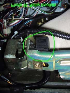
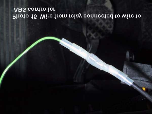
1. Connect the new wire installed in the fusebox to the relay socket connector corresponding to terminal 87a on the relay. Note that this may seem “backwards”. I connected power to this terminal instead of terminal 30 so that when the relay is activated, terminal 87 will not be live. 2. Connect the relay socket connector corresponding to terminal 30 on the relay to the black/green wire removed from the fusebox. To avoid damaging the fuse connector on this wire (to keep the mod reversible), I used a male spade connector on the wire from the relay, slipped it into the fuse connector, and secured the entire assembly with two layers of shrink tubing (see Photo 15). You don’t want this to come apart – if it does, the ABS will shut off. 3. Connect the wire from terminal 6/NSL on the dash switch to the relay socket connector corresponding to terminal 85 on the relay. This feeds power to the relay coil when the dash switch is closed. 4. Connect the relay socket connector corresponding to terminal 86 on the relay to the ground point used to ground the switch illumination bulb (see Photo 7). This grounds the relay coil. 5. Mount the relay socket in a protected spot. I mounted mine inside the knee bar supports (see Photo 16). 6. Protect all wires with spiral wrap tubing or equivalent. Secure the wiring harnesses. Consider the potential movement of the steering column and knee bar in a collision when routing the wiring and locating the relay.
That’s it! Put everything back together, restore power (you did disconnect the battery, didn’t you?), push the antilock switch, and voila! – the ABS light in the instrument panel comes on, informing you the ABS is deactivated.
NOTE: When you push in the switch, the ABS turns off immediately. When you turn the ABS back on, it takes 10 – 15 seconds for the ABS to activate and the warning light to go out.
Enjoy!
Fred Munro ’94 S4
Additional Photos
Related Tech Tips
Revision History
- — Updated
