UrS4/S6 Camshaft Position Sensor Replacement
UrS4/S6 Camshaft Position Sensor Replacement Procedure
Tools needed:
- Zip ties
- 19mm open ended wrench
- H6 allen key
- Paint pen or some sort of precise permanent marker
- Small wire stripper
Parts needed:
- EFI Express generic cam position sensor (used in this tutorial) or Audi OE sensor
- EFI Express wiring harness kit for sensor (recommended)
- Gates 27042 hose, 5/32” inner diameter hose (about 5” max) in order to replace often brittle factory hose that runs by the cam sensor connector. Segment from hard line to front of intake manifold.
- Core support hood/bonnet release clips or zip ties (stock units tend to crack easily upon removal)
If you own one of these cars long enough, sooner or later you’re likely to experience a failure of the camshaft position sensor. As a preventative measure I often like to replace them with every (or every other) timing belt service while doing the camshaft seals.
A failing camshaft position sensor (aka G40 sensor) will typically cause hard starting issues especially once the car is already warmed up. This write up isn’t so much about the symptoms as it is the replacement of the sensor so we’ll keep moving forward with that.
I like to start by removing the front upper core support. Keep in mind that this requires the removal of the plastic hood release cable guides so make sure you have replacements ahead of time or at the very least have zip ties or some other method to secure the hood release cable upon reassembly.
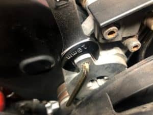
Once the core support is out of the way our next task is to be able to remove the plastic upper timing belt housing cover. In order to accomplish this we must first move the serpentine belt tensioner out of the way as the cover gets sandwiched behind it. Some sort basic H6 allen keys often work well here as you will find clearance is a bit of an issue behind the viscous cooling fan. You do NOT typically need to remove the fan. Use a 19mm wrench to remove the tension from the belt tensioner and insert an allen key or some other object into the hole in the tensioner to hold it securely in the untensioned position. Now remove the 3 bolts that hold the tensioner to the bracket and remove it from the car. The upper plastic belt cover, if still present, can be a bit frustrating as it will sometimes trap the tensioner bolt at the upper left. Use a little patience or remove the plastic cover via the allen bolt on the back.
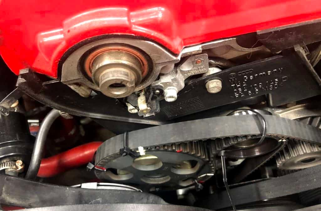
With the serpentine belt tensioner out of the way you should be able to remove the clips that hold the upper timing belt cover in place. It will still require some careful removal to sneak it out of the space so be careful. Now we can see the cam pulley so it is time to zip tie the timing belt securely to the pulley in several locations including TDC (top dead center) and make some reference point marks to insure the belt and pulley remain in perfect alignment.
Removal of the bolt for the cam pulley should not be terribly difficult as it should be torqued to only 48 lb ft. Nonetheless, you will want to find a method to either pin the pulley or prevent it from moving as you remove the bolt. Do NOT use the timing belt itself as leverage for the removal of the bolt as it could jump a tooth or more on the lower cog and you’ll have much more work to do. In my case, a strategically placed screwdriver against the head of the cam sensor bolt followed by a quick blip of my impact gun removed the bolt with zero drama or movement.
With the bolt removed do not immediately pull the camshaft pulley off. You will first want to get some zip ties in place down by the water pump in order to secure the lower section of the timing belt from moving. Once you create slack in the belt by removing the upper pulley you run the risk of the belt stepping off of the lower pulley. It is better to be safe than sorry here.
With the zip ties in place and ready to be tensioned gently wiggle the cam pulley off. (A second set of hands is helpful here to hold the pulley while you secure the lower zip ties to secure the lower portion of the belt.) Carefully lay the cam pulley to one side or the other.
Next we get to remove the actual camshaft position sensor. It looks easy enough but don’t get in a hurry here. The bracket is metal and looks strong but it is made from “pot-metal-mache” as I like to say. The bracket itself can stick to the mounting post even after removing the two allen bolts. Be very careful about prying it loose with a flat bladed screwdriver. The key here is the even application of pressure when trying to pry it free. Start by wiggling it by hand as that is sometimes all that is needed to get it started.
There is one bolt on the plastic rear timing belt shield just under the bottom right corner of the cam position sensor that you will want to remove. We’re going to sneak the wiring harness out from behind this cover so you’ll need a little flexibility with the shield.
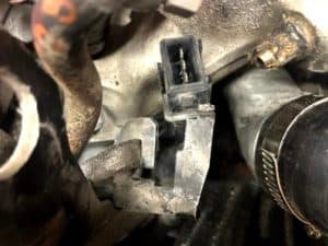
The other end of the cam position sensor is mounted in a bracket at the front of the fuel injection rail. Remove the fuel rail cover if it is still intact on your car and you’ll see the connector. Unplug to top connector and see if you can remove the lower section of the connector from the bracket. Chances are that a short section of hose from a hard metal line to the left leading over to the front on the intake manifold will be in the way. Believe it or not, this can be the toughest part of the entire cam sensor replacement process. If that hose is original to the car it is likely now nearly as hard as a diamond. It is also attached on one end to a hard line section that can flex a bit and you do not want to damage that section of line. Removal took some real patience and careful work with a razor blade and some needle nose pliers. Be sure you have some replacement hose on hand before you dig into this job. (See above referenced parts list for the Gates hose I used to replace mine.)
Once the plug is out carefully remove the original sensor and harness wire from the car while paying attention to the routing method. We’ll obviously want to install the new sensor and harness in a similar fashion.
For this write-up, a new sensor and plug harness kit from EFI Express was used. This is a much cheaper option than buying an original sensor from Audi (if still available) and it works well if you’re willing to do a little work to assemble the wiring harness plug end. You will need to use your drill and a drill bit slightly larger than the mounting pins for the existing cam sensor to gently drill it out until the old sensor releases from the bracket. Use caution here as you don’t want to destroy the bracket. I was able to hold the sensor bracket by hand and carefully drill it out on the workbench. Remove the Phillips screw that holds the existing wiring harness in place and make note of it’s orientation and routing.
When you install the new sensor into the existing bracket you will need to expand the end of the mounting pins to hold the new one in place. These are very delicate and you get one shot at it here so plan ahead. In my case, a new nail setter punch wound up working well to start it then I set a tack over it and applied pressure to flare it out and secure it in place. A bit MacGyver but where there is a will there’s a way!
The new EFI sensor should be wired as follows:
- RED sensor wire (+5v) to vehicle red wire (pin 1 on new connector)
- GREEN sensor wire (signal) to vehicle gray/red wire (pin 2 on new connector)
- BLACK sensor wire (ground) to vehicle brown/red wire (pin 3 on new connector)
It only took 5-10 minutes to make the new sensor plug end with the EFI Express kit. Caveat, the wires are tiny so if you don’t have great eyesight or dexterity you might find this a bit challenging. Remember to clean and transfer the old protective sleeve from the old harness or make a new one to protect the three wires as they route back to the cam sensor bracket. A second set of skilled hands and eyes might be beneficial for some of you here. 🙂
Once you have the new harness ready, simply install it in the same manner as the original. Remember to reinstall the bolt that holds the rear timing cover in place as well.
Next we get to put the cam pulley back on. It is keyed so it should only go on one way. Cut the lower zip ties that held the bottom section of the belt in place. You might also find that it is easier to do if you slightly loosen the roller on the belt tensioner as well but that is up to your discretion. Make sure all of your marks line up as they did during removal. Once again you’ll want to find a way to secure the pulley from turning as you tighten the bolt to 48 lb ft. Also, don’t forget to tighten the tensioner roller bolt to 15 lb ft and use a little Loctite if you loosened it as you don’t want this bolt to back out! Caref
From this point on you simply reinstall the upper timing belt cover carefully and latch it. Then reinstall the serpentine belt tensioner and use the 19mm wrench again to apply enough pressure to pull the allen key (or whatever you used) to relieve the tension during removal. Gently let the tensioner loose onto the serpentine belt. Reinstall your core support and remember to make sure your hood release cable is properly secured.
All done! If this is your first time doing this job, budget about two hours from start to finish. The only parts that typically eat time is building the harness cable if you’re not accustomed to doing that sort of thing and potentially removing the section of hose near the cam sensor harness plug. The rest is pretty simple and straightforward.
Drive safe! Preserve the UrS cars!


