The S-CARS.ORG Used Parts store is not yet accepting online orders however the items shown within are available to purchase. Contact us at editor@s-cars.org for personal order support. Dismiss
While this write-up is specific to the Europrice SSK, it should be applicable to any SSK that replaces the whole shifter assembly, and can be used to R&R the stock shifter assembly if replacing worn parts. Read though the whole procedure first, as there are some reference marks that will be useful during reassembly. Make sure your shifter is in neutral.
Step 1: Remove rear console. Thisis described in a separate write-up. Step 2: Remove front console. This is described in a separate write-up. Step 3: Remove crossmember. Crossmember isheld on with ten (10) 13mm nuts (Figure 1).
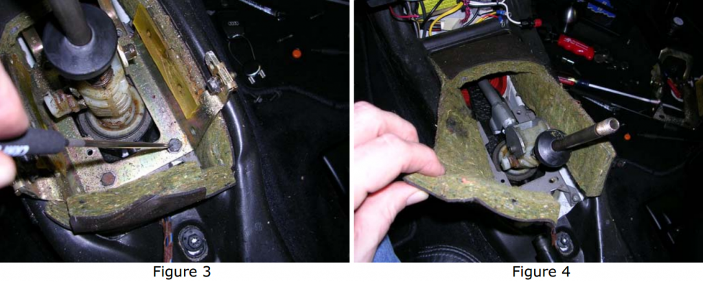
Step 4: Separate exhaust system from downpipe. If you have a Stromung, you will need to remove the center section only. If you have a stock system, you may get away with only having to remove the cats, but will probably have to slide the rest of the system rearward for clearance to work. Step 5: Remove two (2) 13mm retaining bolts from torque rod and shift rod connections (Figure 2). Along extension on a 3/8 ratchet worked for me. You shouldn’t need a universal joint. Mark the torque and shift rods for insertion depth into the forward rods for reference before removal. Step 6: Remove the four (4) 10mm bolts holding the top portion of the stop bracket, and remove the bracket (Figure 3). Take notice of bolt positions asthese hold the rear locator that accepts the pin on the rear of the shift assembly.
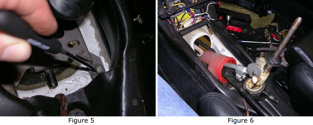
Step 7: Remove the insulation blanket from around the shifter assembly (Figure 4). Step 8: Remove the four (4) 10mm nuts holding the lower portion of the stop bracket, and remove the bracket (Figure 5).
Step 9: Remove the whole shifter assembly with weather boot by lifting up and out towards the rear. You may have to wiggle it slightly to get everythingmoving (Figure 6). Don’t be concerned with the splines on the torque and shifter rods. The forward rods attached to the transmission are not splined on the inside at the connection points. Step 10: Clean and transfer the weather boot to your SSK. Measure and transfer your insertion depth reference marks made in Step 5 to the SSK rods.
Weighting of SSK shift rod
If you do not plan to weight your shift rod, skip this section and go to the Reassembly Tips section. Step 11: Lock your SSK in a vise as shown (Figure 7). Step12: I went to Pep Boys to ask if I could grab some used wheelweights out of the junk bucket next to the tire changer. While I was rummaging through to find the cleanest ones I could, one of the mechanics came up and gave me a box of brand new ones. Score! Anyway, you need to obtain some lead wheel weights. I used approximately 14oz of weights to fill up the hollow in the shift rod.
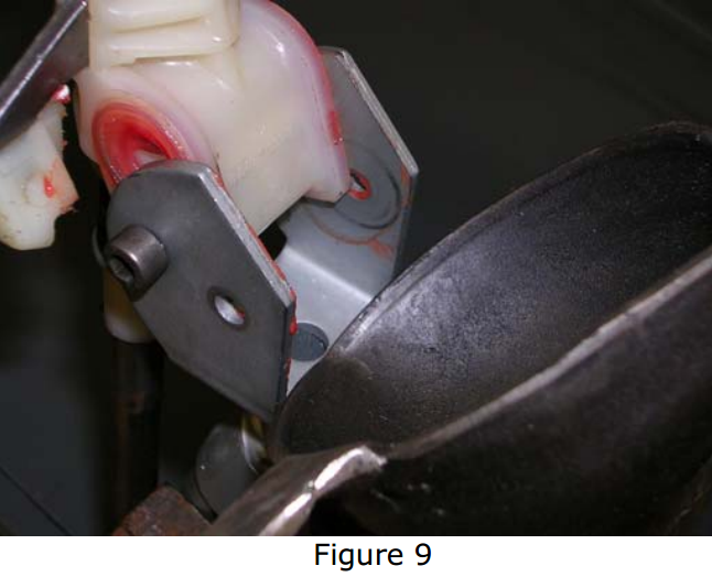
Step 13: Remove the steel clips from the wheel weights. Heat the weights in some type of container. I used a plumber’s ladle (Figure 8) I had which was used for running lead plumbing joints way back when. You can still get these fromplumbing supply housesfor around $35 if you are so inclined. I used an acetylene “B” tank for my heat source. Step 14: Heat the weights until they liquefy, and pour into the shift rod (Figure 9). You should probably wear a mask when heating the lead asI’m sure lead fumes are not good to inhale.
Re-assembly Tips Step 15: I used anti-seize on the torque and shift rod ends to facilitate disassembly again in the future. Reinstall the SSK through the opening inthe floor. Line up the rod connections from underneath. There are no splines onthe inside of the forward rods, so don’t worry about alignment. Get the retaining bolts started to keep everything from coming apart. Step 16: Reinstall the lower portion of the stop bracket, and tighten. Make sure you slip the rubber support over the pin on the rear of the shifter assembly. Reinstall the top portion of the stop bracket. Before tightening the bracket in place, make sure your transmission is still in neutral, and align your side-to-side shifter assembly position (for neutral). Tighten down the top portion of the stop bracket. Step 17: Set the front-to-back shifter assembly position (for neutral) by adjusting to the marks on the torque and shifter rods made in Step 5. Tighten the torque and shift rod retaining bolts. Reinstall the insulation blanket around the shifter assembly. Step 18: Reinstall your front and rear consoles and you’re done.
Sooner or later most UrS4/UrS6 owners find that their rear view mirrors have started to delaminate. Why put up with decreased vision and an ugly mirror when a replacement heated mirror glass can be had for about $85 from your Audi dealer?
Removing and replacing this mirror is far from difficult but I figured it still wouldn’t hurt to put up a quick video FAQ on the subject.
Additional notes: On the later cars the outside mirrors were often a two piece design with a black plastic piece on the bottom that is held in with several screws. Many people find that removing this trim piece allows for easier access to the mounting tabs that hold the mirror glass in place. Naturally, this makes it less likely that you will break these tabs during the removal process. In my case, using the two tire levers and a small flat screwdriver made for quick removal without any damage but you may want to err on the side of caution if you tend to be heavy handed. 🙂
The Bentley shows fewer parts than the above diagram and no Item 19 lock ring. It seems to show pulling the Item 6 cover and the Item 25 flange shaft. It shows the Item 22 round seal (O-ring?) but
does not show the Item 23 radial shaft seal.
Anybody with any BTDT experience on replacing the Item 23 radial shaft seal.
If your A/C system is working OK at highway speeds but seems to fizzle out when in traffic or at a stop light it might be your aux fan resistor. When this part fails there is not enough air flowing through the radiator to lower the refrigerant temps. The resistor is located on the drivers side of the radiator (you may need to remove the headlight to get to it). The part number is 4AO 959 493 and ETKA calls it a series resistor for vehicles with heavy-duty water cooling system and/or trailing towing – ETKA list price is $92.00.
I had a situation where two CDs left the cartridge and decided to impede the changer mechanism. You can probably guess who won (no one, the CD’s were shattered and the unit quit working). The first problem was that after the unit seized I couldn’t even get the cartridge out to discover that there was a disc problem.
I’ve yet to figure out exactly why it quit – unit detected problem and a safety shutdown, the changer drive mechanism overheating, or…..
What I did:
0. First objective – restore basic power to the unit so that I could eject the cartridge.
1. Looked for any unique fuses for the CD assembly – none were found.
2. Reset connector cables to the changer assembly – no effect.
3. Removed the CD Changer assembly from the trunk, removed the cover from the changer, removed the cover and base plate exposing the internal mechanisms, protected by plastic sheets that were semi-transparent.
4. Removed the disc remains.
5. Looked for any loose connections, obvious PCB breaks or components broken by the CD coming apart – none found.
6. Reset two ribbon cable connectors to the base plate, reset the internal power cable connector, etc.
7. Reassembled the unit – no luck.
8. Checked with Audi for the price of a repaired unit – ~ $300, but no units were available.
9. Called about the ads in Quattro Club newsletter – $595 for a whole unit (less head), and none immediately available.
10. Looked for conventional units to replace the changer altogether, looked at Sony since that seems to be who manufactured the unit for Blau. who then seemed to design and add the interface unit, put an Audi sticker on it, and at least double the price. Decided that my only option was a complete replacement – also pricey and time consuming.
11. Repeated steps 3 through 7 again, this time using contact cleaner on the connections and putting a multimeter on the connector plugs to ensure power was getting to the unit (I can send a copy of the wiring diagrams if you’d like them). This time the unit worked after reassembly, and has been working for the better part to three months now (as I shrink waiting for bolts of lightning from the Audi Gods!!!).
Observations:
1. Not even AoA has good diagrams or diagnostics for the 10 disc unit. The best they had available at the dealership was a warning not to use the Alpine diagnostic procedure as it would damage the 10 disc unit. This was on a sheet that said AoA was in the process of creating the 10 disc diagnostics. The date on the sheet was 1992 or 93 as I recall. When pressed in October 1997 the best that AoA could produce was the wiring chart showing chassis connections, but no diagnostic procedures.
2. This appears to be a questionable system. While I don’t strongly object to the music quality of the Audi Bose (it’s one heck of a lot better than the OEM system on my 86 4KCSQ), I’d think that there would be better ways to diagnose and support the customers.
This website uses cookies to improve your experience. We'll assume you're ok with this, but you can opt-out if you wish. Cookie settingsACCEPT
Privacy & Cookies Policy
Privacy Overview
This website uses cookies to improve your experience while you navigate through the website. Out of these cookies, the cookies that are categorized as necessary are stored on your browser as they are essential for the working of basic functionalities of the website. We also use third-party cookies that help us analyze and understand how you use this website. These cookies will be stored in your browser only with your consent. You also have the option to opt-out of these cookies. But opting out of some of these cookies may have an effect on your browsing experience.
As an Amazon Associate I earn from qualifying purchases.
Necessary cookies are absolutely essential for the website to function properly. This category only includes cookies that ensures basic functionalities and security features of the website. These cookies do not store any personal information.
Any cookies that may not be particularly necessary for the website to function and is used specifically to collect user personal data via analytics, ads, other embedded contents are termed as non-necessary cookies. It is mandatory to procure user consent prior to running these cookies on your website.


You must be logged in to post a comment.